The Talon V2 just had too many fussy aspects to it- constant re-alignment of the rotors. So, I decided to sell it to someone who could better appreciate all of its cool carbon fiber and move on to the Turnigy Q450 glass fiber quad frame. It's cheaper, simplier, and doesn't require (or allow!) any sort of alignment. The link below is to the version with the integrated PCB power distribution. For my initial build I used my existing power distribution board instead of the built-in power distribution. I'm also re-using the 18A ESC's and motors from the Turnigy Talon V2 Build, as shown
here. Since the Q450 arms were shorter than the Talon's, I was able to cut out quite a bit of extra motor lead length- saving some weight.
I also upgraded to the new KK2.0 flight controller (FC). The FC I used for the Talon had some sort of electrical failure followed by smoke, so it was no longer usable. Luckily I had a new KK2.0 FC on hand waiting to go. I immediately upgraded the KK2.0 to the new v1.2 firmware from the v1.0 it came shipped from Hong Kong with. Find upgrade instructions
here. I never flew it with the v1.0, so I can't comment on if the v1.2 is any better. The new KK2.0 FC is hands down better than the old FC used on the Talon. Much more stability, nearly hands-off hovering, and all around easier to fly- not to mention much, much easier to set up using the built-in LCD display. Definitely worth the extra $15.
I chose to set up the Quad in "X" mode. Strangely, the pre-drilled holes in the Q450 only support mounting the flight controller in "+" mode orientation, even though the arms are 1/2 white and 1/2 red suggesting that the user fly it in "X" mode. To remedy the situation and allow the flight controller to be properly mounted, I made an adapter plate. Since I didn't have any fiberglass or carbon sheet to make one out of, I used a piece of ABS commonly found at any home improvement store for $0.79 or so- a plastic box cover.
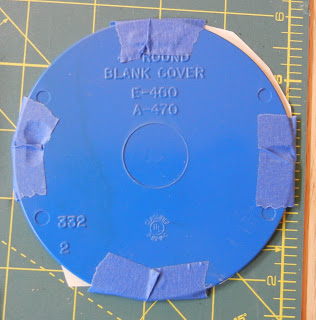 |
| Plastic circular electrical box cover |
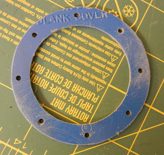
First, I placed the flight controller over a piece of paper and transferred the four mounting hole locations. Next, I used a straightedge to trace a line between diagonal holes to find the center. Then I used a compass to construct perpendicular lines to the diagonals I just created. Finally, I rotated the flight controller 45 degrees, lined the new perp. lines up with the mounting holes, then transferred the hole locations. Once the hole locations were set, I used a compass to create an inner and outer circle.
 |
| Template taped on box cover |
Using this template I drilled each of the mounting screw holes, cut the outside with a bandsaw, and finally cut the center hole with a hole saw.
 |
| Completed adapter plate |
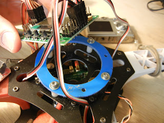 |
| Adapter plate attached to Q450 frame with 4/40 SHCSs and 1/2" spacers |
 |
| KK2.0 FC in place, top view |
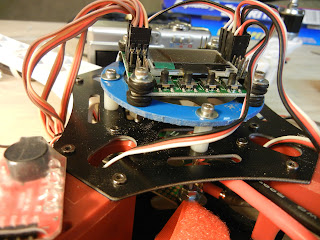 |
| Note the rubber grommets for vibration absorption above and below the FC board |
Since I'm a horrible quad pilot and tend to run into trees, buildings and the ground often, I made a crude roll cage from a piece of 1" wide aluminum and bolted it to the Q450 frame. Crude but effective. It also makes a very nice carrying handle.
 |
| Roll Cage / Carrying Handle in place |
Next steps- lights for night flight and FPV wiring!


What gauge wire did you use between the power distribution board and the battery?
ReplyDeleteI used the power cable that came with the power distribution board- it's pretty heavy gauge, probably 12 gauge wire.
DeleteBuildin' Projects: Q450 Quadcopter Build >>>>> Download Now
ReplyDelete>>>>> Download Full
Buildin' Projects: Q450 Quadcopter Build >>>>> Download LINK
>>>>> Download Now
Buildin' Projects: Q450 Quadcopter Build >>>>> Download Full
>>>>> Download LINK